Rapid manufacturers design and manufacture large quantities of metal or plastic parts every day. All manufactured parts vary in size and physical appearance, and prototype parts, especially, may be unique in the world. However, it can be very challenging to manufacture these plastic or metal parts without deviating from the original design intent. Ensure reasonable tolerances to adhere to correct size and shape. Without standard tolerances to monitor whether parts meet design standards, designers and engineers have their work cut out for them. Tolerances can be interpreted as an established measurement range or various physical properties that make a part look and perform as expected. Tolerances can be in the form of size, appearance, texture, color, etc. It turns out that tolerances are very important in the design and manufacture of CNC machined parts. To make it easier and faster to design and manufacture parts, the International Organization for Standardization (ISO) proposed the ISO 2768 tolerance standard. ISO 2768 is generally divided into two categories, ISO 2768-1 and ISO 2768-2, where ISO 2768-1 deals with linear and angular dimensions, while ISO 2768-2 focuses on the geometric requirements of various features. The ISO 2768 international tolerance standard helps engineers and designers simplify the design and manufacturing process by defining acceptable variation ranges between nominal dimensions and other dimensional values that qualify for fit. In this article, we will discuss the details of ISO 2768 to help you better understand this tolerance standard.
Table of Contents
ToggleWhat is ISO 2768?
ISO 2768 is an international standard for tolerances developed by the International Organization for Standardization (ISO). Its purpose is to simplify the specification of mechanical tolerances in engineering drawings. The ISO 2768 tolerance standard facilitates the design and manufacturing process, promoting smoother collaboration and cooperation between different companies. The standard mainly applies to parts manufactured by CNC machining. When specific tolerances are not explicitly specified, ISO 2768 should generally be followed. The ISO 2768 standard is relevant to a wide range of industries including: automotive, aerospace, electronics and electrical industries.
ISO 2768 is divided into two parts – ISO 2768-1 and ISO 2768-2. These parts define a level of mechanical accuracy to simplify technical drawings. Please note that all tolerance limits are in millimeters.
Part 1 – General tolerances for linear and angular dimensions, the accuracy of which is divided into four tolerance classes.
- M – Medium tolerances
- F – Fine tolerances
- C – Coarse tolerances
- V – Very coarse tolerances
Part 2 – Geometric Tolerances of Features. The accuracy classes or tolerance classes here are H, K and L.
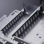
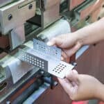
For example, a design drawing specifying the tolerance standard ISO 2768-mK means that such parts must meet the “Medium” tolerance range of Part 1 and the tolerance class “K” of Part 2. ISO 2768-mK is commonly used in manufacturing sheet metal parts. However, rapid manufacturers also choose ISO 2768-fH for CNC machined parts. Since ISO 2768-mK is a global industry standard, AN-Prototype’s CNC machining services for metals adhere to the ISO 2768-f standard, while plastic parts adhere to the ISO 2768-m standard.
Part 1: General tolerances ISO 2768-1
ISO 2768-1 is designed to simplify design drawings and applies to linear and angular dimensions such as exterior dimensions, interior dimensions, step dimensions, diameter, radius, distance, outer radius and chamfer height, etc. If general tolerances in accordance with ISO 2768 should apply, ISO 2768 should be indicated in or near the title block of the drawing, followed by the tolerance class (for example: ISO 2768-f).
Table 1 - Linear Dimensions
Permissible deviations in mm for ranges in nominal lengths | Tolerance Class Designation (Description) | |||
f (fine) | m (medium) | c (coarse) | v (very coarse) | |
0.5 up to 3 | ±0.05 | ±0.1 | ±0.2 | – |
over 3 up to 6 | ±0.05 | ±0.1 | ±0.3 | ±0.5 |
over 6 up to 30 | ±0.1 | ±0.2 | ±0.5 | ±1.0 |
over 30 up to 120 | ±0.15 | ±0.3 | ±0.8 | ±1.5 |
over 120 up to 400 | ±0.2 | ±0.5 | ±1.2 | ±2.5 |
over 400 up to 1000 | ±0.3 | ±0.8 | ±2.0 | ±4.0 |
over 1000 up to 2000 | ±0.5 | ±1.2 | ±3.0 | ±6.0 |
over 2000 up to 4000 | – | ±2.0 | ±4.0 | ±8.0 |
Lists the tolerance table corresponding to level 4 accuracy. You can choose the most appropriate tolerance standard based on CNC machining capabilities and design requirements. Note: For dimensions below 0.5 mm, the tolerance should be stated next to the relevant nominal dimension.
Table 2 - External Radii and Chamfer Heights
Permissible deviations in mm for ranges in nominal lengths | Tolerance Class Designation (Description) | |||
f (fine) | m (medium) | c (coarse) | v (very coarse) | |
0.5 up to 3 | ±02 | ±0.2 | ±0.4 | ±0.4 |
over 3 up to 6 | ±0.5 | ±0.5 | ±1.0 | ±1.0 |
over 6 | ±1.0 | ±1.0 | ±2.0 | ±2.0 |
NOTE: Likewise, tolerances below 0.5 mm should be noted next to the relevant dimension.
Table 3 - Angular Dimensions
Permissible deviations in mm for ranges in nominal lengths | Tolerance Class Designation (Description) | |||
f (fine) | m (medium) | c (coarse) | v (very coarse) | |
up to 10 | ±1º | ±1º | ±1º30′ | ±3º |
over 10 up to 50 | ±0º30′ | ±0º30′ | ±1º | ±2º |
over 50 up to 120 | ±0º20′ | ±0º20′ | ±0º30′ | ±1º |
over 120 up to 400 | ±0º10′ | ±0º10′ | ±0º15′ | ±0º30′ |
over 400 | ±0º5′ | ±0º5′ | ±0º10′ | ±0º20′ |
Table 3 defines general tolerances for angles/angular dimensions. It should be noted that the tolerance units for angles are degrees and minutes.
Application of ISO 2768-1
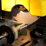
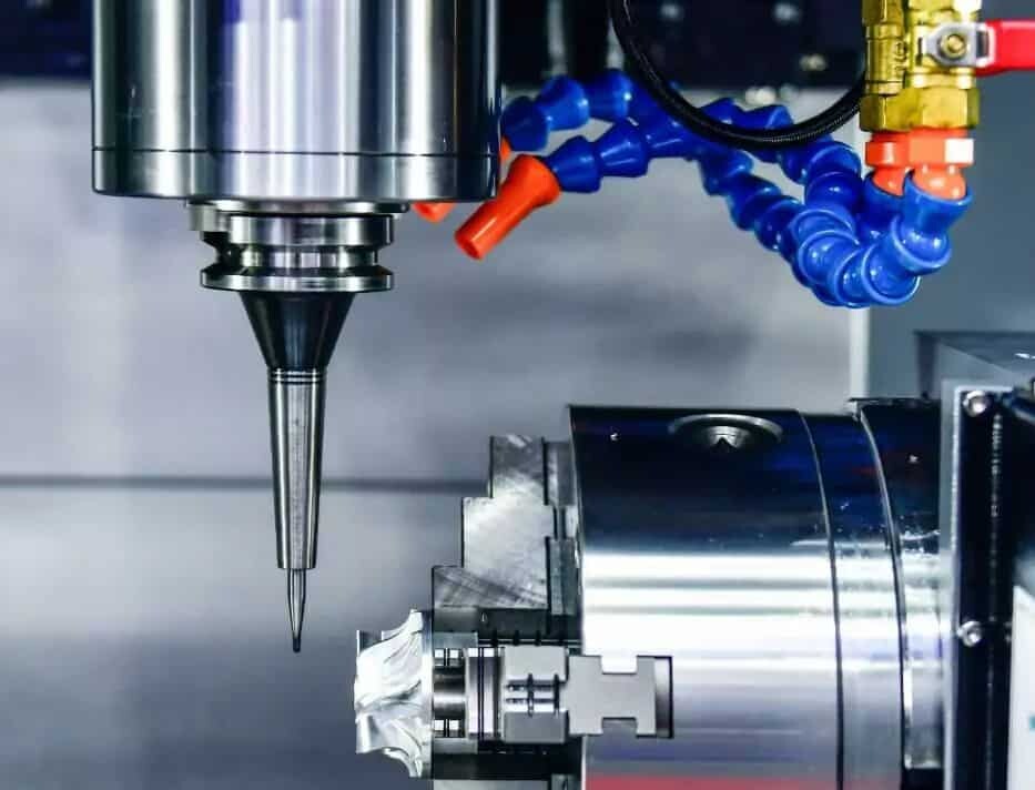
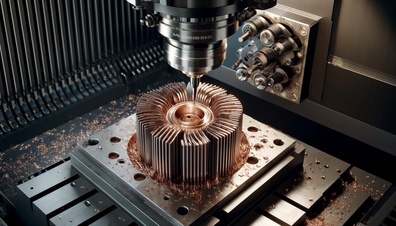
ISO 2768-fH is of great significance to CNC processing of medical parts, aerospace parts, and automotive parts. It helps ensure designers and engineers work together to create parts with the required dimensions, angles and radii. CNC machining is becoming increasingly popular in modern manufacturing processes. Engineers responsible for CNC machining combine a variety of design, drawing, measuring and computer skills to program to manufacture metal or plastic parts. Rapid prototyping also ensures that manufactured prototypes meet expectations according to ISO 2768-1 tolerance standards. Mold manufacturing also utilizes this standard to ensure correct mold design, thereby making production more efficient.
Part 2: General tolerances ISO 2768-2
ISO 2768-2 refers to geometric tolerances for features that do not have separate tolerance indications and includes general geometric tolerance ranges for flatness, straightness, cylindricity, and roundness. ISO 2768-2 includes tolerance levels 3 – H, K and L:
For example, instead of defining upper and lower limits, the designer defines the area between two references (i.e., parallel planes) so that the manufactured surface should lie between them. When you place a caliper to measure these two surfaces, you will get several different values due to the roughness of the surfaces. We define datums as dimensional references to control the acceptable degree of deviation. These values should be within the tolerance range.
Table 4 - General Tolerances on Straightness and Flatness
Ranges of nominal lengths in mm | Tolerance Class | ||
H | K | L | |
up to 10 | 0.02 | 0.05 | 0.1 |
above 10 to 30 | 0.05 | 0.1 | 0.2 |
above 30 to 100 | 0.1 | 0.2 | 0.4 |
above 100 to 300 | 0.2 | 0.4 | 0.8 |
above 300 to 1000 | 0.3 | 0.6 | 1.2 |
above 1000 to 3000 | 0.4 | 0.8 | 1.6 |
Table 4 defines flatness and straightness tolerance classes. Taking the compressor example again, the contact surface between the compressor and the base and the contact surface between the base and the engine are important, so their flatness tolerances are specified in the drawings. Straightness tolerance refers to the degree of variation within a specified straight line on that surface. Another use is to allow for the degree of bending or twisting of the axis of a part.
Table 5 - General Tolerances on Perpendicularity
Ranges of nominal lengths in mm | Tolerance Class | ||
H | K | L | |
up to 100 | 0.2 | 0.4 | 0.6 |
above 100 to 300 | 0.3 | 0.6 | 1.0 |
above 300 to 1000 | 0.4 | 0.8 | 1.5 |
above 1000 to 3000 | 0.5 | 1.0 | 2.0 |
Verticality distance is in millimeters. Similar to flatness, we define the gap between two planes to be less than the allowable deviation in Table 5. Our goal is to achieve a 90 degree angle.
Table 6 - General Tolerances on Symmetry
Ranges of nominal lengths in mm | Tolerance Class | ||
H | K | L | |
up to 100 | 0.5 | 0.6 | 0.6 |
above 100 to 300 | 0.5 | 0.6 | 1.0 |
above 300 to 1000 | 0.5 | 0.8 | 1.5 |
above 1000 to 3000 | 0.5 | 1.0 | 2.0 |
Table 6 shows the symmetry tolerances on the part on the datum plane.
Table 7 - General Tolerances on Circular Run-Out
Ranges of nominal lengths in mm | Tolerance Class | ||
H | K | L | |
0.1 | 0.2 | 0.5 | |
This universal tolerance allows the designer to choose the tolerance level that best suits the requirements. For example, if the part is to be used in a CNC project with tight tolerance requirements, it would be wise to choose a smaller tolerance range. Conversely, if high-volume parts are manufactured for lower tolerance applications, a wider tolerance range will be more cost-effective.
Application of ISO 2768-2
ISO 2768-2 is important when it comes to where two surfaces of a component come into contact with each other. The flatness of both surfaces needs to be noted in the drawing before manufacturing, which helps ensure the accuracy of parts manufactured in batches. It also helps determine the acceptable degree to which a part can bend or twist.
What industries is ISO 2768 relevant to?
The ISO 2768 tolerance standard is used in many industries including:
Aerospace: In the aerospace sector, where safety is critical, ISO 2768 helps ensure consistent quality of aerospace components.
Automotive: Since manufactured automotive parts often come from different regions, ISO 2768 ensures consistency in the manufacturing process and helps in a seamless assembly process.
Medical devices: Accuracy is critical for medical devices, and this standard provides medical manufacturers with a reliable basis for consistency.
Electronic: Ensuring that electronic components fit together perfectly is critical for electronic products, and ISO 2768 helps manufacturers achieve this goal.
Mechanical Engineering Services: The ISO 2768 tolerance standard is highly applicable to mechanical engineering, where precise tolerances are critical for the proper functioning of components, machinery, and equipment.
Manufacturing: ISO 2768 tolerance standards are relevant to most manufacturing industries, including automotive, aerospace, medical, electronics, etc., helping to ensure the consistency and compatibility of parts produced by different manufacturers or suppliers.
Industrial Design: The ISO 2768 tolerance standard is relevant to companies involved in industrial design as it provides guidelines for specifying tolerances in technical drawings to ensure the correct fit of the designed product for its intended function.
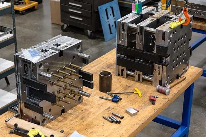
Tooling and mold manufacturing: ISO 2768 tolerance standards are widely used in the mold manufacturing industry to determine the tolerances of molds and tooling components to ensure that the shape and size of manufactured plastic parts meet expectations.
ISO-2768: Closing the global manufacturing gap
ISO-2768 is frequently referenced in manufacturing design and manufacturing processes, and is a testament to the relentless pursuit of precision and consistency in production. ISO-2768 addresses general tolerances for linear and angular dimensions that lack separate tolerance indications. These general tolerances are further classified based on the type of production and complexity of the part. It is a globally recognized universal tolerance standard for mechanical engineering drawings. It ensures consistency in quality and fit of parts manufactured in different regions. The standard reduces ambiguity by specifying general tolerances, providing clarity to rapid manufacturers. With clearer guidelines, ISO 2768 provides rapid manufacturers with significant cost savings by reducing waste.
The Importance of Tolerances in Manufacturing and Quality Control
Tolerances play an important role in ensuring that each part is manufactured to the correct specifications. In the process of manufacturing parts, tolerances play an important role and are very critical. Important roles in these tolerances include:
More detailed understanding of manufactured parts. Every rapid manufacturer wants to make the best possible product, but this may not be possible due to unclear requirements specifications. Tolerances help manufacturers understand the allowable range of deviations in size, shape, etc. of a product.
Control the manufacturing cost of parts. When parts are designed to tight tolerances, manufacturing costs tend to be high, and vice versa. Therefore, when applications are not required in harsh environments, manufacturing parts with loose tolerances can save costs.
Avoid mistakes. Tolerances help provide the maximum and minimum measurement for the deviation of a part within which the product can work efficiently. This helps in rapid manufacturing by being able to make parts that better fit the job requirements, thus speeding up the production process.
Facilitates assembly between parts. Some components are made from two or more parts joined together, so tolerances help ensure that the parts are sufficiently compatible with each other.
Contributes to more productive communication between designers and mechanics. This helps ensure the product is of the agreed quality by using the correct tolerances.
AN-Prototype’s on-demand manufacturing services
We detail that ISO 2768-1 and 2 are standards with different characteristics that help them suit different applications. AN-Prototype has always been at the forefront of advanced manufacturing technology. We offer on-demand manufacturing services that match international standards such as ISO 2768, ensuring manufactured parts meet stringent quality standards. We utilize the latest manufacturing technologies to ensure precision, speed and efficiency on every project. A decade-long rapid prototyping business serving a variety of industries including aerospace, automotive, medical, robotics and more highlights its versatility and commitment to excellence. AN-Prototype is proud to offer custom part solutions including ISO 2768 tolerances and special tolerances to meet each customer’s unique needs.
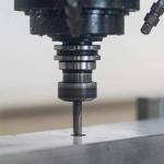
Factors such as materials, workmanship and cost should also be considered when determining the correct tolerance level for a part or product. For example, if you want to build precision metal parts to tight tolerances for your project, then CNC machining would be a good choice. CNC machine tools are highly precise and can produce parts with very tight tolerances. Typically CNC machining tolerances range from ±0.001″ to ±0.0001″.